

Views: 0 Author: Site Editor Publish Time: 2026-07-03 Origin: Site


Unplanned valve leakage frequently leads to environmental compliance failures, serious safety hazards, and significant production downtime. Every unnoticed drop of lost media directly erodes your operational efficiency. It also puts onsite personnel at severe physical risk. Therefore, we must frame pressure testing not as a simple quality assurance checkbox, but as a critical risk-mitigation investment before installation. Skipping this vital verification phase often allows microscopic manufacturing flaws to evolve into catastrophic system failures down the line.
This article provides a practical technical framework for evaluating current testing protocols. It helps you understand real-world leakage tolerances accurately. You will learn how to parse vendor documentation effectively. Ultimately, you will discover how to confidently select verifiable components for your most demanding, high-stakes industrial applications.
Prevention over reaction: Rigorous shell and seat testing identifies microscopic structural flaws and seal imperfections before they scale into systemic leaks.
Standards dictate reliability: Evaluating manufacturers based on strict adherence to API, ASME, and FCI standards ensures objective performance baselines.
The "zero leakage" reality check: All valves have allowable leakage tolerances; proper evaluation requires matching the specific standard class to the application's required sealing performance.
Vendor accountability: Sourcing components like an OEM ball valve directly from a manufacturer with transparent, documented in-house testing eliminates third-party quality gaps.
Failing to verify valve integrity before system integration carries massive financial penalties. It disrupts normal facility operations heavily. Undetected leaks demand immediate emergency maintenance. They force unplanned shutdowns and halt production lines completely. Operational managers often underestimate the compounding financial impact of a single failed component. A compromised seal allows valuable process fluids to escape continuously. This degrades overall yield and inflates operational expenses significantly.
Early failure symptoms rarely look like massive blowouts. You must train maintenance teams to identify subtle physical indicators early. Watch closely for unexplained downstream pressure drops. Look for cross-contamination between separated process lines. Closed systems often emit unusual acoustic signals. High-frequency hissing frequently points directly to internal seat bypass. Technicians can use ultrasonic acoustic detectors to pinpoint these invisible bypass leaks accurately. Identifying these symptoms early prevents catastrophic mechanical failures.
Consider the overall lifecycle cost of the equipment. A comprehensive pressure verification process requires a minimal upfront budget. However, post-installation troubleshooting scales exponentially. Extracting a welded component from an active pipeline consumes massive labor resources. You need special work permits, heavy scaffolding, and extensive safety protocols. Line replacements and hazardous material cleanups drain maintenance budgets rapidly. Proper verification serves as highly effective insurance against these extreme downstream expenses. It prevents minor defects from triggering major environmental fines.
We break down verification methodologies into specific solution categories. They validate overall structural integrity and internal sealing performance separately. Manufacturers cannot rely on a single uniform test for all functions. Valve Testing protocols adapt dynamically to the final operating environment. These categories ensure the entire assembly operates safely under extreme mechanical stress.
Shell testing evaluates the physical body of the component. Technicians typically use hydrostatic pressure at 1.5 times the maximum rated working pressure. They flood the body chamber completely and cap all open ends. This process verifies the pressure-containing boundaries comprehensively. It exposes casting porosity, micro-cracks, and weak body joints. The heavy liquid pressure forces any microscopic defect to reveal itself visibly. Operators inspect the exterior body carefully for any weeping or sweating during the hold period.
Seat closure testing examines the internal sealing mechanism directly. It checks the ability of the internal closure element to hold pressure. Testers apply hydrostatic or pneumatic pressure to one side of the closed mechanism. They measure any fluid escaping past the seat on the opposite side. This evaluates the exact mating surface between the moving parts. It ensures the soft or metal seats function according to their engineered design specifications.
Different industrial environments demand distinct testing mediums. Water serves general industrial needs exceptionally well. It remains safe because liquid does not compress significantly under pressure. However, cryogenic or ultra-high-purity systems require completely dry mediums. Technicians use dry nitrogen or filtered compressed air for these specialized applications. Using the wrong test fluid often contaminates the internal components permanently. Trapped moisture causes rapid corrosion when exposed to certain reactive process gases later.
Objective evaluation requires strict technical benchmarks. You cannot rely on vague manufacturer promises regarding performance. We use standardized industry codes to verify supplier claims accurately. These frameworks remove subjectivity from the procurement process entirely. They provide a common language for engineers and manufacturers globally.
Authoritative standards govern these procedures heavily. API 598 dictates inspection and verification baselines for refinery operations. It covers leakage rates for resilient and metal-seated components. ANSI/FCI 70-2 governs control seat leakage classifications specifically. ASME B16.34 outlines the exact pressure and temperature ratings required for safe structural design. Adhering to these documented standards guarantees a minimum baseline of physical safety.
Many buyers fall for the "zero leakage" myth. True absolute zero leak simply does not exist in mechanical engineering. Engineering standards define specific, mathematically acceptable leakage rates. Class IV allows a measurable percentage of rated flow capacity to pass. Class VI measures leakage in tiny distinct bubbles per minute. Be highly skeptical of vendors claiming absolute zero leakage unconditionally. They must state the exact standard code they test against. Otherwise, their promises hold no technical weight.
You must match tolerance to your specific application. Deciding how strict the standard needs to be depends entirely on the media handled.
Common ANSI/FCI 70-2 Leakage Classes Overview |
||
Leakage Class |
Maximum Allowable Leakage |
Typical Test Medium |
|---|---|---|
Class II |
0.5% of rated valve capacity |
Air or Water |
Class III |
0.1% of rated valve capacity |
Air or Water |
Class IV |
0.01% of rated valve capacity |
Air or Water |
Class V |
0.0005 ml per minute per inch |
Water |
Class VI |
Varies by port size (Bubbles/min) |
Air or Nitrogen |
Hazardous gases require Class VI bubble-tight shutoff explicitly. Toxic chemical lines demand the strictest possible tolerances to protect personnel. Standard cooling water loops function perfectly well under Class III or IV parameters. Over-specifying leakage classes increases manufacturing costs unnecessarily. Under-specifying them leads to dangerous environmental leaks.
Testing procedures frequently suffer from basic human error. These execution risks lead to false positives or highly dangerous false negatives. A flawed test provides a dangerous illusion of safety. Operators must control the physical environment tightly to ensure accurate data.
Many technicians misinterpret simple pressure drops during the procedure. Trapped air inside a liquid-filled body compresses over time. This compression lowers the gauge reading artificially. System elasticity causes rubber test hoses to expand slightly under heavy pressure. Thermal expansion or contraction alters internal fluid pressure readings dramatically. If cold water enters a warm steel body, it expands. These physical phenomena easily mimic a structural leak. Technicians must bleed all air before pressurizing the system.
Inadequate dwell times present another major danger. Technicians often rush the holding period to meet daily production quotas. Micro-leaks usually take several minutes to register on analog pressure gauges. A thick steel casting might take longer to reveal internal porosity. We recommend strictly following the minimum dwell times mandated by API 598. Larger components require exponentially longer observation periods. Shortening this time invalidates the entire certification.
Poor preparation ruins accurate readings consistently. Testing a dirty component masks inherent manufacturing defects. Machining debris creates artificial temporary seals. It also damages soft polymer seats permanently during closure. Applying incorrect clamping forces on the test bench warps the metallic body. This warping causes the internal seats to leak artificially.
Failing to bleed all trapped atmospheric air before pressurization begins.
Using uncalibrated or physically damaged analog pressure gauges.
Testing equipment at incorrect ambient room temperatures.
Applying excessive external clamping force, distorting the body shape.
Leaving thick protective greases on the internal sealing surfaces.
Procurement strategy matters just as much as the testing methodology itself. Buying from unverified sources introduces massive operational risks into your facility. You need a transparent supply chain to ensure long-term reliability. Secondary distributors often lack the technical capability to verify product integrity.
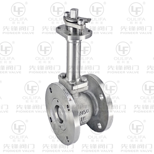
Sourcing an OEM Ball Valve provides a distinct engineering advantage. Original equipment manufacturers maintain tighter control over the quality assurance loop. Buying through fragmented secondary distributors often breaks the traceability chain completely. Direct OEM sourcing guarantees authentic raw materials. It also ensures the factory follows standardized assembly procedures strictly. Manufacturers possess the exact technical drawings needed to troubleshoot complex issues. They understand the exact torque specifications required for proper seat assembly.
You must demand verifiable documentation for every critical purchase. Paperwork proves the physical execution of the quality plan. Always request certified Material Test Reports for the raw metal castings. Ask for documented pressure certificates tied directly to traceable serial numbers. These documents protect you during external safety audits. They prove you installed fully compliant equipment.
Implement a strict evaluation process during the vendor vetting phase. Do not accept generic marketing brochures as proof of quality.
Do they operate fully calibrated, internationally certified testing equipment?
Do they allow independent third-party inspectors to witness the procedures?
Can they provide a comprehensive digital logging history for every unit?
Do they use automated hydraulic test benches to remove human error?
Evaluating these specific facility capabilities separates premium manufacturers from basic assemblers. It ensures your vendor takes physical safety as seriously as you do.
Audit your current supply chain documentation immediately to ensure complete traceability. Align your required engineering leakage classes strictly with your actual media hazard levels. Request continuous video evidence or third-party verification for high-pressure application components. Shift from treating quality checks as assumed features to treating them as verifiable procurement requirements.
Comprehensive integrity verification serves as the strongest predictor of long-term success. Relying on documented evidence prevents catastrophic failures and protects your personnel. Consult factory engineering teams early in your design phase. They will help you match exact testing standards to your specific flow control challenges successfully.
A: Hydrostatic testing uses liquid, typically water, to evaluate high-pressure structural safety. Water does not compress significantly, making it safer for structural body checks. Pneumatic testing uses gas, like compressed air or nitrogen, to detect minute micro-leaks in the seats. We perform gas testing at lower pressures to minimize explosive expansion risks.
A: Installation errors often compromise factory-tested equipment. Severe pipe strain twists the metal body out of alignment. Improper flange torquing creates uneven gasket pressure. Debris remaining in the newly welded line frequently scores the internal seats upon first closure. Extreme thermal differences between the test bench and the operating environment also cause unexpected metal expansion.
A: Class VI represents the most stringent standard for soft-seated control equipment. It establishes a maximum allowable leak rate measured in distinct bubbles per minute. Engineers specify this exact standard when an application demands virtually bubble-tight shutoff. It is essential for safely handling hazardous, toxic, or highly flammable process gases.
A: Hold times depend entirely on the specific industry standard applied, such as API 598. The required duration varies significantly based on the nominal pipe size, pressure class, and the specific test performed. Larger components require much longer dwell times. This allows minute physical leaks to become visible to the testing technician.


