Views: 0 Author: Site Editor Publish Time: 2026-10-14 Origin: Site
Flow control dictates the rhythm of liquid and semi-liquid filling lines. Milliseconds in actuation time directly impact dosing accuracy, product waste, and overall line speed. Facility managers and process engineers face a constant tension between capital expenditure and operational efficiency. You must balance the low initial cost of manual valves against the high-throughput demands and strict Clean-in-Place (CIP) requirements that necessitate automation. Selecting the right valve type forms the foundation for scaling production. It ensures hygienic compliance while minimizing labor bottlenecks across the facility.
This engineering evaluation provides the technical criteria needed to optimize your fluid handling architecture. You will learn how actuation speed affects throughput, what infrastructure upgrades are necessary, and how to mitigate implementation risks. Understanding these mechanical differences prevents costly downtime and ensures your processing lines meet strict sanitation standards.
Actuation Speed Dictates Throughput: Pneumatic valves provide the rapid, repeatable response times required for high-speed filling and emergency shutoffs, whereas manual valves are limited by human operator speed and consistency.
CIP/SIP Integration: Automated hygienic valve actuation is mandatory for modern, hands-free Clean-in-Place (CIP) and Sterilize-in-Place (SIP) protocols, eliminating the risk of human error during sanitation cycles.
Infrastructure Prerequisites: Transitioning to pneumatic systems requires a reliable, clean compressed air infrastructure and PLC integration, representing a higher upfront investment compared to standalone manual valves.
Filling lines demand rigorous operational baselines. High-cycle frequency is standard across modern packaging facilities. Valves must open and close hundreds of times per hour without mechanical degradation. Precise shut-off is non-negotiable to prevent dripping and product giveaway. A sanitary butterfly valve for filling lines must feature a zero dead-leg design. This geometry prevents product stagnation and bacterial growth within the piping matrix. Fluid must flow across the valve disc without pooling in crevices.
When handling viscous fluids like yogurt or liquid soaps, the valve disc must shear the fluid column cleanly. Any hesitation in the closing stroke results in stringing or dripping at the fill nozzle. This ruins package seals and requires manual wipe-downs. The valve acts as a strict gatekeeper. It holds back head pressure from the supply tank and releases fluid in exact, timed increments. These applications require rapid on/off isolation rather than fine flow modulation. Butterfly valves in filling systems travel from 0% to 100% instantly. They operate fully open or fully closed. This binary action ensures precise volumetric and gravimetric dosing. Proportional flow adjustment is rarely the objective at the filling nozzle.
Hygienic compliance dictates the physical design of the valve body and seals. Components must meet 3-A, FDA, and EHEDG standards. The actuation method cannot compromise the sanitary boundary of the process fluid. Smooth internal finishes, typically polished to a 15-20 Ra (Roughness Average), are mandatory. Crevice-free discs ensure that sticky products wash away easily during cleaning cycles. The elastomeric seats must sit flush against the stainless steel body, leaving no microscopic gaps for bacteria to colonize.
Valve selection directly impacts system integration. Standalone manual stations require physical operator presence for every batch. Fully networked SCADA systems rely on automated components to execute complex recipes. Your choice determines the complexity of the broader control architecture. Upgrading a facility requires mapping out these integration points early. You must decide if the process warrants local control or centralized, programmable logic.
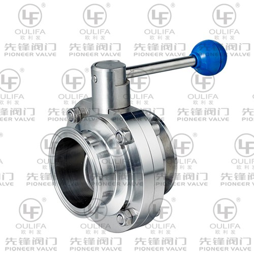
Physical actuation relies on direct human interaction. Operators use multi-position pull handles, squeeze levers, or gear operators. These mechanisms provide direct tactile feedback during operation. You can feel the seating resistance through physical contact. A manual sanitary butterfly valve locks into specific positions via notched stainless steel plates. This mechanical locking prevents the valve from drifting open under line pressure. The simplicity of this design makes installation straightforward and immediate.
Manual operation excels in specific, low-frequency scenarios. Low-volume batch processing often justifies manual control. Maintenance isolation points and bypass lines rarely require automation. Facilities with limited compressed air infrastructure benefit heavily from these standalone units. You can install them anywhere in the plant without running pneumatic tubing or electrical conduit.
Common applications for manual valves include:
Pump suction and discharge isolation for maintenance.
Manual ingredient addition ports on mixing tanks.
CIP bypass loops used only during weekly deep cleans.
Gravity drain valves on the bottom of holding vessels.
However, manual operation carries hidden operational burdens. Labor requirements for daily operation and sanitation are substantial. Operators must walk the line, physically turning each handle during CIP cycles. Inconsistent torque application accelerates seat wear. When operators force a handle closed, they compress the elastomer unevenly. Emergency shut-offs suffer from slower human reaction times. High-frequency use introduces significant ergonomic strain on operators, leading to fatigue and potential wrist or shoulder injuries.
The lack of automation also limits process visibility. A manual valve cannot send a position signal back to a central control room. Operators must visually verify if the valve is open or closed. This reliance on human verification introduces the risk of cross-contamination. If a single valve is left in the wrong position during a wash cycle, cleaning chemicals can mix with the product. This reality restricts manual valves to non-critical or highly supervised process nodes.
Automated hygienic valve actuation transforms fluid control from a manual task into a synchronized process. Pneumatic actuators convert compressed air into quarter-turn mechanical motion. Spring-return, or single-acting, models use air to open and heavy-duty internal springs to close. Double-acting models use air pressure for both directions. The rack and pinion design inside the actuator ensures smooth, consistent torque delivery across the entire 90-degree stroke.
Pneumatic power remains the automation standard over electric alternatives for specific reasons. Pneumatic systems deliver the ultra-fast response times necessary for high-speed dosing. Electric actuators move too slowly for rapid filling cycles. They rely on gear reduction motors that take several seconds to cycle. Pneumatic actuators dump air instantly, snapping the valve shut. Electric actuators are better suited for complex, slow-moving flow modulation where speed is secondary to positional accuracy.
A pneumatic sanitary butterfly valve offers unmatched speed and precision. Response times occur in fractions of a second. This instantaneous action translates to exact volumetric filling. It eliminates costly product giveaway at the nozzle. When the scale or flow meter registers the target weight, the PLC cuts the signal. The pneumatic valve closes immediately, shearing the fluid stream cleanly without residual dripping.
Successful deployment requires reliable infrastructure. You need clean, dry compressed air, commonly termed instrument air. Moisture in the air lines will corrode the internal springs of the actuator. Solenoid valves, often NAMUR mounted directly to the actuator body, direct the airflow. Limit switches and proximity sensors monitor the valve status. This network ensures the actuator operates efficiently and communicates its exact position back to the central PLC. Without this infrastructure, pneumatic automation is impossible.
To maintain pneumatic systems, facilities must implement:
Coalescing filters to remove compressor oil from the air lines.
Refrigerated air dryers to drop the dew point and prevent internal condensation.
Properly sized air headers to prevent pressure drops during simultaneous valve actuations.
Regular inspection of solenoid exhaust ports to ensure they remain free of debris.
Response time defines dosing accuracy in any packaging environment. Pneumatic systems provide instantaneous, repeatable actuation every single cycle. Manual valves depend entirely on variable operator speed and physical strength. Pneumatic superiority becomes obvious during emergency shutoff scenarios. Automated valves isolate flow immediately upon fault detection. If a downstream pipe ruptures, the PLC drops the air pressure, and the spring-return actuator closes the valve instantly.
Sanitation protocols highlight stark operational differences between the two methods. Manual CIP execution requires operators to physically open and close valves in a specific sequence. This introduces human error and slows down turnaround times. Pneumatic actuators enable programmable, automated sequencing. The control system pulses the valves hands-free during cleaning cycles. This pulsing allows cleaning solutions to wash over the sealing faces, ensuring complete sanitation without dismantling the line.
Lifecycle expenditure requires careful analysis of capital and operational variables. Capital expenses for automated systems include the valve, actuator, air lines, solenoid, and PLC I/O cards. Operational expenses cover labor, maintenance, product yield, and compressed air energy. Over a multi-year lifecycle, automated systems offset their high initial costs through increased throughput. They drastically reduce labor hours spent on manual batching and cleaning. They also prevent expensive product loss through tighter dosing control. Evaluating a manual vs pneumatic sanitary butterfly valve means weighing upfront hardware costs against long-term production gains.
Maintenance profiles and failure modes differ significantly. Manual handles suffer from physical degradation and broken locking notches. Operators often induce seat wear by forcing the disc past its natural seating point. Pneumatic systems eliminate this ergonomic abuse but introduce new variables. You must monitor for pneumatic seal wear, air leaks, and actuator spring fatigue. Replacing an actuator O-ring requires different skills than swapping a manual handle.
Operational Feature | Manual Actuation | Pneumatic Actuation |
|---|---|---|
Actuation Speed | 1 to 3 seconds (operator dependent) | Milliseconds (instantaneous action) |
Dosing Accuracy | Low to Moderate | Extremely High |
CIP/SIP Integration | Requires physical human intervention | Fully automated and programmable |
Infrastructure Needed | None (Standalone operation) | Compressed air, PLC, solenoids, wiring |
Primary Failure Mode | Handle degradation, operator-induced wear | Air leaks, internal O-ring wear, spring fatigue |
Ergonomic Impact | High strain during high-frequency use | Zero strain (hands-free operation) |
Ultra-fast closing speeds introduce severe fluid dynamics risks. Water hammer, or hydraulic shock, can rupture lines and damage expensive processing equipment. When a pneumatic valve snaps shut on a fast-moving fluid column, the kinetic energy spikes line pressure. You must manage this energy. Mitigation strategies include installing flow control exhaust silencers on the actuator. These restrict the air exhaust, slightly slowing the closing speed. Two-stage actuation can also cushion the final closing phase.
Infrastructure deficiencies cause erratic valve behavior and production delays. Pressure drops in the plant's compressed air system lead to sluggish response times. Valves may fail to close completely against high fluid pressure. Prevent this by properly sizing air supply lines based on peak demand. Install dedicated air receivers near high-demand filling manifolds. Ensure your compressors output a consistent 80 to 90 PSI to keep the actuators functioning at their rated torque.
Retrofitting existing lines presents distinct engineering challenges. Upgrading manual valves to pneumatic systems requires careful spatial planning. Actuators add significant height and weight to the piping matrix. Spatial constraints often complicate installation in tight skids. Control wiring integration demands scheduled downtime. You must ensure the new actuator is fully compatible with the existing valve body stem. Mismatched stems and drive squares will strip the mechanical connection over time.
Follow these steps when retrofitting a manual valve to pneumatic:
Measure the available clearance above the valve to ensure the actuator will fit without hitting adjacent pipes.
Verify the stem geometry matches the actuator's female drive.
Select a mounting bracket that provides enough standoff distance to clear any pipe insulation.
Route the new pneumatic tubing away from high-heat sources or caustic washdown zones.
Update the PLC logic to include the new valve's open and closed limit switch feedback.
Environmental factors also play a role in implementation. Washdown environments expose pneumatic components to harsh caustic chemicals. Standard aluminum actuators will corrode quickly under these conditions. You must specify stainless steel or epoxy-coated actuators for heavy washdown zones. Protect the solenoid exhaust ports with check valves or route them outside the washdown area. Water ingress into the pneumatic cylinder will destroy the internal seals and springs.
Evaluating an OEM pneumatic sanitary butterfly valve requires strict vendor vetting. Look for a vertically integrated sanitary butterfly valve manufacturer. They should produce both the valve body and the actuator in-house. This ensures perfect mechanical alignment between the stem and the drive gear. Demand complete material traceability through certified Mill Test Reports (MTRs). Assess their custom configuration capabilities for specialized applications, such as jacketed valves for temperature-sensitive fluids.
Seat materials must match the specific process fluid perfectly. The manufacturer should guide this selection process based on chemical compatibility and temperature ranges. EPDM works well for general applications and standard CIP temperatures. FKM handles high-fat dairy products and oils without swelling. Silicone suits extreme temperature variations but lacks mechanical tear resistance. PTFE provides broad chemical resistance for acidic juices. The chosen material directly influences the required actuation torque.
Prioritize vendors with reliable after-sales support and inventory management. Rebuild kits must be readily available to minimize unplanned downtime. Elastomer seats degrade over time and require routine replacement. Ensure the valve features standardized actuator mounting pads, such as ISO 5211. This standardization allows you to swap actuators without replacing the entire valve body. Responsive technical support is critical when troubleshooting pneumatic control loops or limit switch wiring issues.
Request detailed flow data before making a purchase. The manufacturer must provide accurate Cv (flow coefficient) values for their valves. This data allows your process engineers to calculate pressure drops across the filling manifold. Undersized valves will restrict flow and increase fill times. Oversized valves reduce the velocity of the fluid, potentially allowing particulates to settle in the line. Proper sizing ensures the valve operates efficiently within your specific hydraulic parameters.
The choice between manual and pneumatic actuation fundamentally dictates your production ceiling. It is a choice between capital conservation and operational scalability. Manual systems keep initial costs low and simplify installation. Pneumatic systems unlock high-speed throughput, eliminate sanitation bottlenecks, and provide precise dosing control. Your decision shapes the daily workflow of your operators and the overall yield of your facility.
Apply a clear heuristic for your facility upgrades. Specify manual valves for isolation, maintenance, and low-frequency manual batching. Specify pneumatic valves for all active filling nozzles. Use them in automated CIP circuits and high-throughput production lines requiring rapid on/off cycling. Mixing these technologies strategically allows you to optimize your budget while maximizing line efficiency.
Take the following steps to optimize your filling line:
Audit your current manual valve cycle times to identify production bottlenecks.
Assess your facility's compressed air capacity, focusing on pressure stability during peak shifts.
Calculate the potential product savings achieved by upgrading to millisecond shut-off speeds.
Request technical drawings and flow coefficient values from a qualified manufacturer.
Standardize your valve mounting pads to simplify future automation upgrades across the plant.
A: Pneumatic valves actuate in milliseconds to seconds depending on air pressure and actuator size. They provide instantaneous flow control. Manual valves depend entirely on operator speed and physical strength. A manual actuation usually takes 1 to 3 seconds, making it unsuitable for precision dosing.
A: Yes. Many modern sanitary valves feature standardized mounting pads. Operators can remove the manual handle and bolt on a pneumatic actuator directly. This upgrade occurs without removing the valve body from the process line, minimizing system downtime.
A: Standard operating pressures typically range between 60 to 90 PSI (4 to 6 bar). The system requires filtered, dry instrument air. Moisture and particulates in the air supply will cause internal corrosion and premature failure of the pneumatic actuator.
A: Pneumatic valves are vastly superior for CIP protocols. The central control system can pulse them automatically to clean the valve seat. This hands-free operation ensures thorough sanitation without human intervention or the risk of operator error.
A: The valve body maintenance remains identical. However, pneumatic actuators introduce additional internal components like O-rings, pistons, and springs. These require periodic inspection and lubrication. Fortunately, pneumatic actuation eliminates the risk of operator-induced mechanical damage to the valve stem.
A: Spring-return (normally-closed) actuators are the standard for filling lines. They ensure a fail-safe shutoff in the event of power or air loss. This mechanism immediately stops the flow, preventing catastrophic product spills and maintaining plant safety.